
OBDII conversion - troubleshooting time
 01-30-2008, 08:44 PM
#51
Senior Member
True Car Nut
Thread Starter

Join Date: Aug 2004
Location: In your garage, swipin' da lug nutz
Posts: 3,067
Likes: 0
Received 1 Like
on
1 Post

Got tired of the engine bay looking like a patchwork quilt, so I.....
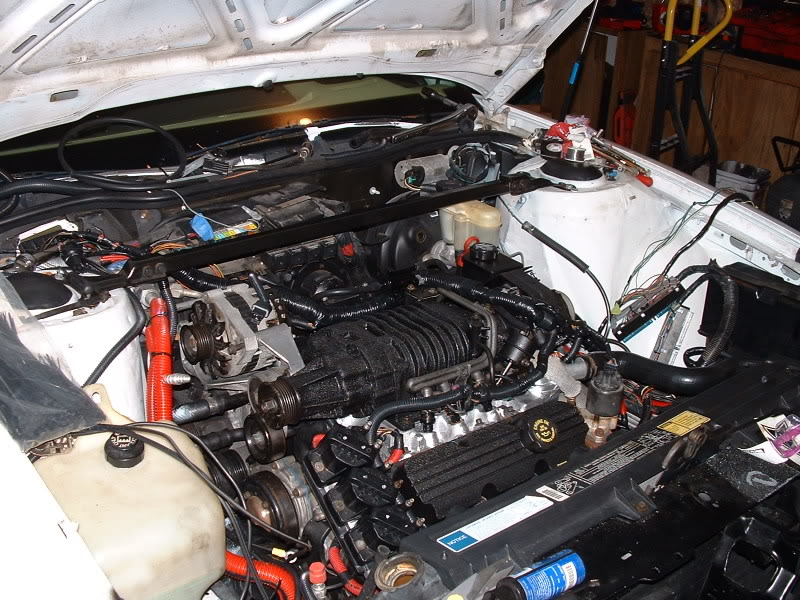
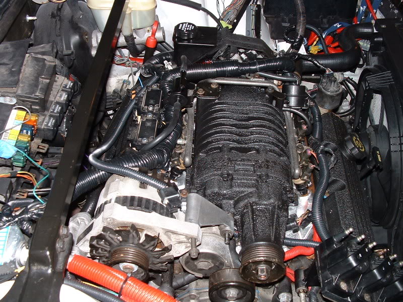
Since I already had the supercharger off of the car for refurbishment, I thought I would dig a little deeper. Then one thing led to another...but in the end, it looks a bajillion times better.
Modifications to the harness were numerous. I extended the alternator hookup, heavilly extended the egr leads, among other things. I also redone the evap purge system, which I modded once before. The purge solenoid was located right on the boost solenoid, but now is located where the MAP array is.
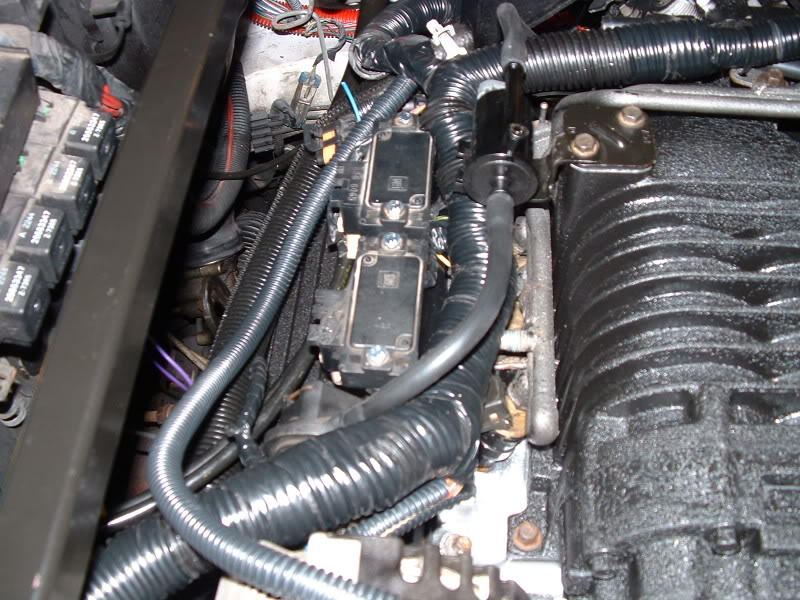
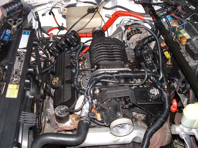
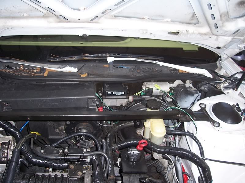
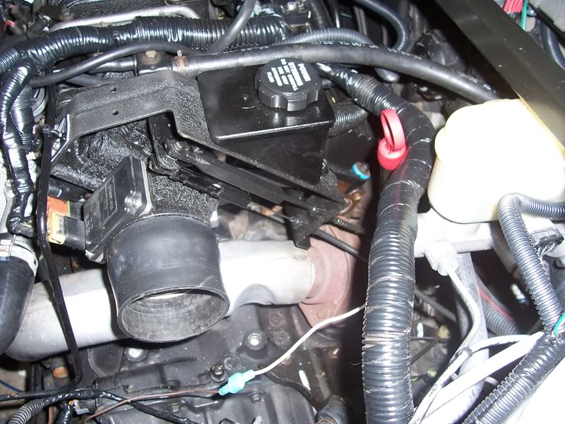
Other shots I took while I was at it. Keep in mind that this is a work in progress and more detailing will go into it the further along I go.
Since I already had the supercharger off of the car for refurbishment, I thought I would dig a little deeper. Then one thing led to another...but in the end, it looks a bajillion times better.
Modifications to the harness were numerous. I extended the alternator hookup, heavilly extended the egr leads, among other things. I also redone the evap purge system, which I modded once before. The purge solenoid was located right on the boost solenoid, but now is located where the MAP array is.
Other shots I took while I was at it. Keep in mind that this is a work in progress and more detailing will go into it the further along I go.
 01-30-2008, 09:31 PM
#52
Senior Member
Posts like a Camaro

Join Date: Jul 2004
Location: Canada, Ontario
Posts: 1,090
Likes: 0
Received 0 Likes
on
0 Posts
I hqve been reading this thread since it started, thats a really big job, what did you spray on your valve covers and supercharger?
Great infor
Great infor
01-30-2008, 10:28 PM
#53
Senior Member
True Car Nut
Thread Starter
Join Date: Aug 2004
Location: In your garage, swipin' da lug nutz
Posts: 3,067
Likes: 0
Received 1 Like
on
1 Post
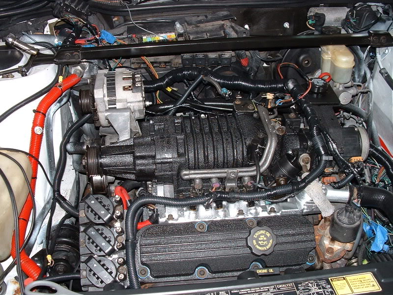
Krylon Wrinkle Coat. Wren used it on his supercharger first, with great success. He then used it on his valve covers (aluminum F-body). I followed suit, along with painting the throttle body, TB bracket, and a few other brackets. The LIM is painted in Duplicolor high-temp aluminum paint (higher temp than their engine paint).
I'll have more stuff done tomorrow, I think. I may be checking out an excellent parts car, and I may very well get it if I can get it transported here (its an hour away).
I'll have more stuff done tomorrow, I think. I may be checking out an excellent parts car, and I may very well get it if I can get it transported here (its an hour away).
02-08-2008, 05:24 PM
#54
Senior Member
True Car Nut
Thread Starter
Join Date: Aug 2004
Location: In your garage, swipin' da lug nutz
Posts: 3,067
Likes: 0
Received 1 Like
on
1 Post
More updates.
This past week I have been finishing up a few loose ends (no pun intended) with wiring in the existing relays (A/C, high and low speed fans, and fuel pump), and I verified all of them to work through applying power to the appropriate pins at the PCM harness heads. I'll have to go to the junkyard sometime soon to snag another KS harness head, and I will need to build a sine wave to square wave converter for the missing 2k speed output needed for the chime module. But other than those two little things, the PCM is ready to go in
There are other things too that need to be addressed, such as the A/C and cruise control. Those are accessories, and I can work on those more in-depth after I verify the PCM works.
The end is near :P
02-09-2008, 09:37 PM
#55
Senior Member
Posts like a Camaro

Join Date: Nov 2007
Location: MN
Posts: 1,172
Likes: 0
Received 0 Likes
on
0 Posts
with allt his wire extending, and re-routing, how are you connecting it all? are you soldering in the engine bay or do you have some kind of quick-connectors?
02-10-2008, 06:53 AM
#56
Senior Member
True Car Nut
Thread Starter
Join Date: Aug 2004
Location: In your garage, swipin' da lug nutz
Posts: 3,067
Likes: 0
Received 1 Like
on
1 Post
In the engine bay, I soldered every extension, and used heat shrink around the junctions. Internally, I used vampire taps to allow the harness to come out of the car should it need to come out (plus, this IS prototyping afterall...once everything is verified to work, I can easily go back and solder all the connections in the cabin). My testing so far shows my connections in the engine bay are spot-on (Every time I extended a wire, I checked for continuity before continuing), so all is well in that regard.
The few spots that I did use taps inside the engine bay are to bridge circuits that no longer exist. For instance, the old-style AC system uses two pressure switches between the programmer and the PCM, The new style does away with those switches and instead uses a sensor on a completely different circuit. So, for the time being...I put taps in between the wires to bypass the switches. If it doesn't work, taps can come out and switches plugged back in.
The few spots that I did use taps inside the engine bay are to bridge circuits that no longer exist. For instance, the old-style AC system uses two pressure switches between the programmer and the PCM, The new style does away with those switches and instead uses a sensor on a completely different circuit. So, for the time being...I put taps in between the wires to bypass the switches. If it doesn't work, taps can come out and switches plugged back in.
02-15-2008, 08:36 PM
#57
Senior Member
True Car Nut
Thread Starter
Join Date: Aug 2004
Location: In your garage, swipin' da lug nutz
Posts: 3,067
Likes: 0
Received 1 Like
on
1 Post
Yet another update...
I broke down and bought a "tester" PCM from the Daytona u-pull-it (1997 Olds vin K), knowing full well it probably wouldn't work. Which it didn't. But that'* cool...because it enabled me to finish testing my mods to the harness, like ensuring I get 5 volts to several sensors, making sure the fuel pump works (and it does), check engine light (works too), et cetera. Oh yes...I get spark too
NOW THEN...on to another issue I ran across earlier. The 1993 PCM has two speed outputs (or rather 2 output frequencies)....a 4k pulse, which is used for cruise and dash, and a 2k pulse, which goes to the chime module and that pulses sole purpose is to enable/disable T2V. Since the OBD2 computer only has a 4k output, that leaves T2V hanging in the breeze.
SO....my solution to that WAS to build a sine-to-square wave converter (total cost would be less than a coffee and donut), tune it to a 2k output, and tap off of the VSS for input In theory, this should work...but adds more to the process than there should be. So a much simpler option would be to either A) Just wire it to a switch so I can choose between normal and firm whenever I want, or B) leave it fully disconnected. Thing is, at what setting will it be at if I do option B?
I am SO CLOSE now.
I broke down and bought a "tester" PCM from the Daytona u-pull-it (1997 Olds vin K), knowing full well it probably wouldn't work. Which it didn't. But that'* cool...because it enabled me to finish testing my mods to the harness, like ensuring I get 5 volts to several sensors, making sure the fuel pump works (and it does), check engine light (works too), et cetera. Oh yes...I get spark too
NOW THEN...on to another issue I ran across earlier. The 1993 PCM has two speed outputs (or rather 2 output frequencies)....a 4k pulse, which is used for cruise and dash, and a 2k pulse, which goes to the chime module and that pulses sole purpose is to enable/disable T2V. Since the OBD2 computer only has a 4k output, that leaves T2V hanging in the breeze.
SO....my solution to that WAS to build a sine-to-square wave converter (total cost would be less than a coffee and donut), tune it to a 2k output, and tap off of the VSS for input
In theory, this should work...but adds more to the process than there should be. So a much simpler option would be to either A) Just wire it to a switch so I can choose between normal and firm whenever I want, or B) leave it fully disconnected. Thing is, at what setting will it be at if I do option B?I am SO CLOSE now.
02-20-2008, 01:12 PM
#58
Senior Member
True Car Nut
Thread Starter
Join Date: Aug 2004
Location: In your garage, swipin' da lug nutz
Posts: 3,067
Likes: 0
Received 1 Like
on
1 Post
Yet another update...
Got the cruise module bolted in, along with the modded cable. I really like how this cable turned out.
Worked on the OBD2 cable plugin today. Only 5 wires are needed to make it work Got it screwed into the dash, by the parking brake.
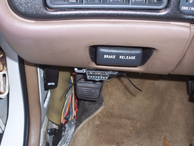
AND IT WORKS TOO!


There'* gonna be codes, and I'm actually glad there are...lets me know things are working, diagnostic-wise.
Got the cruise module bolted in, along with the modded cable. I really like how this cable turned out.
Worked on the OBD2 cable plugin today. Only 5 wires are needed to make it work
Got it screwed into the dash, by the parking brake.AND IT WORKS TOO!
There'* gonna be codes, and I'm actually glad there are...lets me know things are working, diagnostic-wise.
02-20-2008, 01:22 PM
#59
Junior Member
Posts like a Ricer Type-R

Brad, T2V will act like normally steering at all times without the 2k pulse. So you'll have slightly heavy steering in parking lots. Normal above those speeds.
Why don't you tap off the CPS 18x pulse and run it through a frequency divider, and just feed it directly to T2V? I don't have my FSMs handy to verify that.
Why don't you tap off the CPS 18x pulse and run it through a frequency divider, and just feed it directly to T2V? I don't have my FSMs handy to verify that.
02-20-2008, 01:47 PM
#60
Senior Member
True Car Nut
Thread Starter
Join Date: Aug 2004
Location: In your garage, swipin' da lug nutz
Posts: 3,067
Likes: 0
Received 1 Like
on
1 Post
If T2V acts stiff w/o a pulse, that'* fine by me. The SSE is stiff at all times, so I am used to the force that is needed.
In order for T2V to work correctly, it has to be based off of vehicle speed, not engine speed. Voltage divider would not work, even with the 4k signal. Reason being is that the 2k/4k signals are a constant frequency. It'* the AMPLITUDE of those freequencies that change. And from my research, it'* hard to effectively chop a squarewave signal in half. The sine-to-square wave converter would be the best option IMO, if I want automatic T2V.
For me, a switch would work just as good, or leaving it disabled altogether.