
aftermarket alarm *(viper 791 xv install)* updated diagrams


 08-26-2004, 12:33 AM
#12
Senior Member
True Car Nut

if the alarm has more outputs sure u can have more the one shock sensor central yea but most of your wires are under the column and vibrations travel the longest through wires so i'd say the column
08-26-2004, 07:55 AM
#13
Senior Member
True Car Nut

Originally Posted by Kennginn
is there a way to install more then one shock sensor?
08-26-2004, 09:03 AM
#14
Senior Member
True Car Nut

Join Date: Apr 2004
Location: Three Oaks, Michigan
Posts: 4,879
Likes: 0
Received 3 Likes
on
3 Posts

What if you were to put one on all for fender areas? Would that be the only way to protect your car from somebody perhaps kicking the tires and such? or would one mounted on the coloumn detect all of that?
-justin
-justin
08-26-2004, 09:12 AM
#15
Senior Member
True Car Nut
quote="opensourceguy"]What if you were to put one on all for fender areas? Would that be the only way to protect your car from somebody perhaps kicking the tires and such? or would one mounted on the coloumn detect all of that?
-justin[/quote]
One shock sensor is sufficient for most passenger vehicles. Pickup truck beds are isolated from the cab with the rubber bushings so another one is needed if the bed is to be protecetd.
There are both interior and exterior proximity sensors that can be integrated to help with the tire kickers but nothing will really prevent that except parking the thing in your garage at home
08-26-2004, 08:24 PM
#16
Senior Member
True Car Nut

Join Date: Dec 2002
Location: Halifax, Canada 91SSE / 97SSEi
Posts: 5,857
Likes: 0
Received 0 Likes
on
0 Posts
How'* that viper install going?
I have the same system in Knight Fire.... but I had it installed at the shop.
It'* a really nice system. I hope your install goes well.
I have the same system in Knight Fire.... but I had it installed at the shop.
It'* a really nice system. I hope your install goes well.
09-02-2004, 07:44 PM
#17
Senior Member
Posts like a Camaro
Thread Starter

Join Date: Feb 2003
Location: Indianapolis, IN / West Lafayette
Posts: 1,004
Likes: 0
Received 0 Likes
on
0 Posts
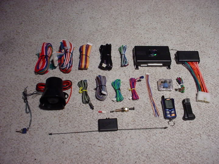
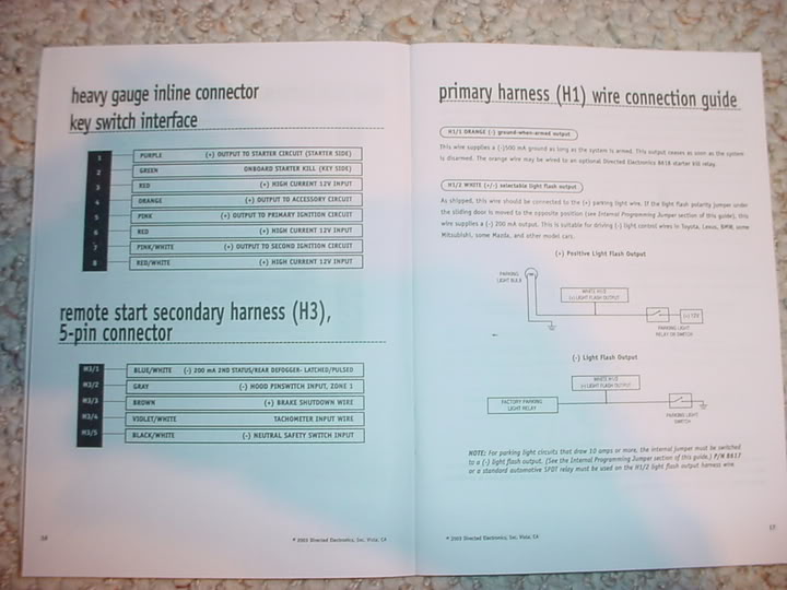
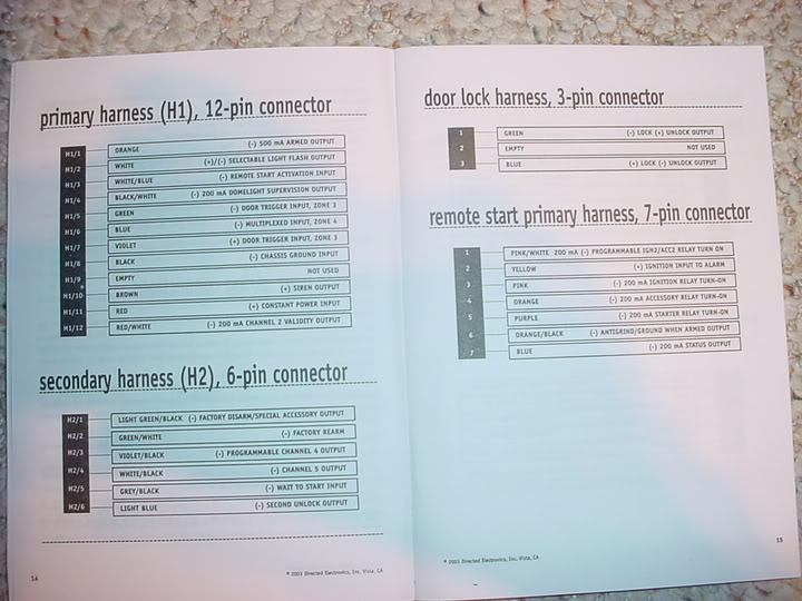
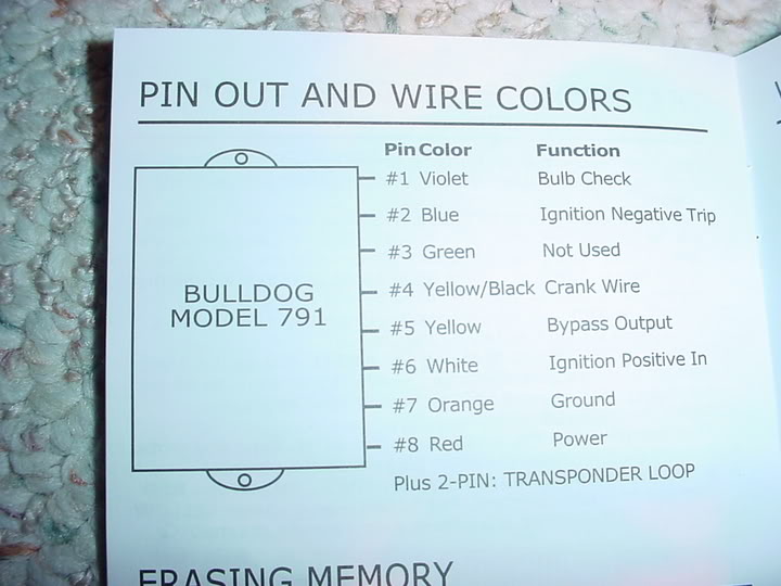
ok i wont have time to install it this weekend because i will be out of town but here are some pics of the alarm and some diagrams...if there are any wiring experts out there that could help me figure out what wires connect to what (just to make sure i know what i am doing) and what is up with this bulldog wiring on the bypass do i really need to use all of those wires...its almost like wiring in a alarm system itslef...and i know i will need a relay for the trunk but are there any other required relays i need to get to make this alarm work? help on wiring diagrams would be greatly apperciated.
09-07-2004, 08:15 PM
#19
Senior Member
Posts like a Camaro
Thread Starter
Join Date: Feb 2003
Location: Indianapolis, IN / West Lafayette
Posts: 1,004
Likes: 0
Received 0 Likes
on
0 Posts
anyone know if i can eliminate any of the wires on the bulldog bypass or not and does anyone wanna help with the diagrams for the alarm (i have a good idea but i could always use a little input)
09-07-2004, 08:33 PM
#20
Senior Member
True Car Nut
There is some descrepancies in these diagrams. Look at yours, then look at these:


PASSKEY (VATS) INSTALLATION (GM only)
This FUEL SYSTEM shutdown anti-theft system is based on a pellet (resistor) built into the steel shaft of the
ignition key. When the key is inserted into the ignition switch, the VATS (vehicle anti-theft system) computer
reads the value of the resistor to make sure that it matches the programmed code and then turns on the fuel
system so the vehicle can be started.
1. Locate two (2) wires in an orange vinyl tube coming down from the ignition switch. This tube will contain
two (2) WHITE 22 ga. wires or one WHITE and one PURPLE wire.
2. If you have the PURPLE and the WHITE wires, cut the WHITE wire in two. If your vehicle has two (2) WHITE
wires, you will need to test both of these wires with the ignition key turned to the ON or RUN position.
One will show ground and the other will show positive voltage. Cut the WHITE wire that shows voltage in two.
3. Attach the GREEN wire to the key switch end of the cut WHITE wire. See Making Connections. Page 2,
figure 1.
4. Attach the YELLOW wire to the remaining end of the cut WHITE wire.
5. Attach the WHITE wire to the ignition I wire (white heavy gauge wire from the remote starter or from the 4-
relay pack) that is tied into the ignition wire on the vehicles ignition switch harness.
6. Attach the RED wire to a constant 12V wire fused at 3 amps.
7. Connect the ORANGE wire securely to ground.
8. Connect the BLUE wire to the smaller of the two (2) WHITE wires on the remote starter.
9. The PURPLE and the YELLOW with BLACK stripe wires are not used and should be taped up.
10. Put the key in the ignition switch and start the vehicle.
11. Wait until the L.E.D. light on the 791 goes out.
12. Turn off the vehicle the system has learned the resistor value.