
4T60E Shifter Assembly holding pin/nail
 09-01-2012, 03:08 AM
#1
Member
Posts like a V-Tak
Thread Starter

Join Date: Sep 2005
Location: Tempe, AZ
Posts: 73
Likes: 0
Received 0 Likes
on
0 Posts

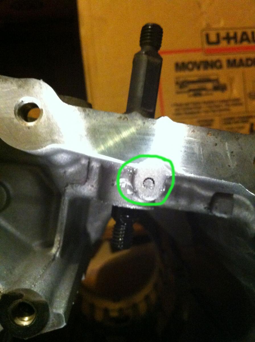
So as I was disassembling the tranny, the pin started coming coming off but the head and part of the body just kind of snapped and broke. Any idea how to take it out at this point? Should I just drill into it?
 09-01-2012, 08:57 AM
#3
Retired


Certified Car Nut


That pin is what holds the shift linkage rod in. It only goes in one way and comes out the same way. Yea, your going to have to drill it out. But, why are you removing it?
__________________
Retired Administrator
Retired Administrator
09-01-2012, 06:39 PM
#4
Member
Posts like a V-Tak
Thread Starter
Join Date: Sep 2005
Location: Tempe, AZ
Posts: 73
Likes: 0
Received 0 Likes
on
0 Posts
Mike: I was following a dissassebly guide and they took it out. Thinking about it now I guess its really not that necessary, but since its halfway out I better get a new one to put all the way back in. I will probably end up drilling it this afternoon.
Also, while I was repainting the shell this afternoon, I heard something fall out and looked around and found this:
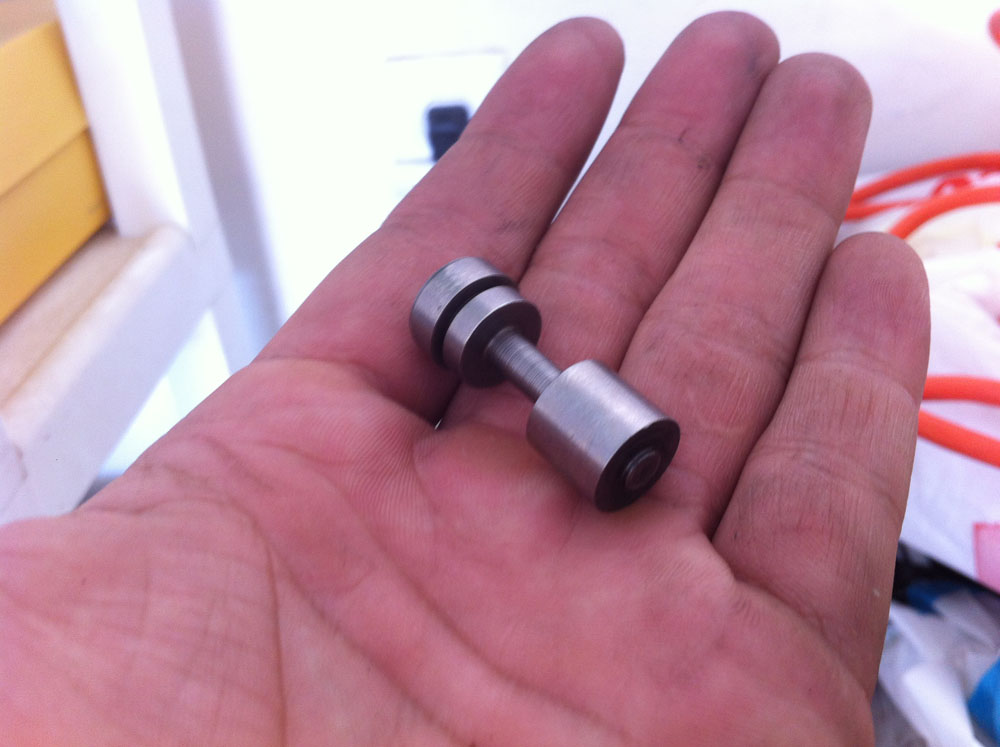
Any idea where this goes?
Also, while I was repainting the shell this afternoon, I heard something fall out and looked around and found this:
Any idea where this goes?
09-01-2012, 07:47 PM
#5
Retired
Certified Car Nut
Wow, its been awhile since I have had one of these trans taken apart. If it came out of the case, I wonder if came from the vacuum modulator port???
__________________
Retired Administrator
Retired Administrator
09-01-2012, 08:19 PM
#7
Retired
Certified Car Nut
Are you playing with this thing without a manual? Atta boy!!!
I think this might be it, I cannot find any other part that looks like it besides item #34
I think this might be it, I cannot find any other part that looks like it besides item #34
__________________
Retired Administrator
Retired Administrator
09-01-2012, 08:28 PM
#8
Member
Posts like a V-Tak
Thread Starter
Join Date: Sep 2005
Location: Tempe, AZ
Posts: 73
Likes: 0
Received 0 Likes
on
0 Posts
It definitely fits in the port.
It looks in figure 35 they're using a stick or something to push it in. Im guessing from this figure that the side on my ring finger goes in first and index finger connects to modulator assembly (Part 32)?
And I am using the High performance rebuild video thats being sold on eBay. No patience for ATSG paper manuals ;-D (Despite having ch 6 in the FSM memorized at this point lol)
09-01-2012, 08:32 PM
#9
Retired
Certified Car Nut
I don't think it actually connects to the modulator, but you appear to be correct in the idea that they are using some sort of threaded rod to put it back in. I always thought, tip it on its side, bang with hammer till it falls out works pretty good too.
What'* wrong with paper manuals? Easier to read than draggin a tv to the garage. LOL.
What'* wrong with paper manuals? Easier to read than draggin a tv to the garage. LOL.
__________________
Retired Administrator
Retired Administrator
09-02-2012, 12:16 AM
#10
Member
Posts like a V-Tak
Thread Starter
Join Date: Sep 2005
Location: Tempe, AZ
Posts: 73
Likes: 0
Received 0 Likes
on
0 Posts
Easier to read than draggin a tv to the garage.